


SAFETY IN ELEVATORS & SAFETY GEARS
There are about 20 million elevators in service around the world, with more than 1 million new elevators being commissioned every year. Thanks to safety standards for elevators, these elevators transport billions of people every day. Wherever there is an elevator that affects the lives of so many people, ensuring the safety of passengers should be the most important issue for those involved in the elevator business.
'Elevator safety' means that the elevator can safely transport a number of people or loads equivalent to the nominal load for which the elevator is designed from one floor to another at the specified speed. In order for elevators to be safe, 6 Safety Components are defined according to the 2014/33/EU Lifts Directive. Two of these six vital safety components, the Overspeed Governor and the Safety Gears, work in cooperation to ensure safety.
Safety devices in terms of braking mode in order of historical development:
- Instantaneous Safety Gear
- Sudden braking & bumper effect,
- Progressive Safety Gear
can be analyzed in three parts.
According to EN 81-20/-50 standards; safety devices with sudden braking are used in cases where the declared speed of the elevator does not exceed 0,63 m/s. Since the stopping distance of the safety device, which performs the full clutch action on the guide rails almost instantaneously, is small, the car and guide rails are overstressed. If the rated speed exceeds 0.63 m/s, a sliding safety device must be used. 'Buffer-acting brakes' have been phased out. In this article, we will mainly examine sliding type braking systems.
Parachute systems, which are extremely important for the safety of passengers in high-speed elevators, are not even as much on the agenda as the coating of the preferred cabin or the button panel model during the contract phase to be signed between cabin manufacturers and contractors. However, the least dangerous parts of elevators are the parts that are visible to the end user; the invisible parts such as safety devices are the parts where the risks are the highest.
Parachute Systems, which find a place in EN 81-20/-50 standards under the name of 'safety device', are defined as "A mechanical device used to stop the downward movement of the cabin, counterweight or counterbalance weight and to keep them immobilized on the guide rails by activating in case of excessive acceleration or breakage of the suspension device."
The simplest way to stop a moving object within a certain period of time by absorbing its kinetic energy is to convert its kinetic energy into heat through friction. In general, when the brake mechanism is activated, one half of the brake attached to the cab is brought into contact with the rail by springs, while the other half is pressed against the rail in accordance with the geometry of the roller and its inclined seat. The rail is compressed between these two parts. In the meantime, the springs with low stiffness stretch. The resulting normal force turns into frictional force and starts to consume the kinetic energy of the car. This friction continues until the car stops.
Figure 1- Parts that make up the Progressive Safety Gear; Zorlu branded, Z-03 model brake
The task of the Overspeed Governor, one of the safety devices of the elevator, is to ensure that the safety rope is in sufficient tension and to disable the elevator when this rope loosens. A minimum tension force of 300 Nm must be transmitted from the overspeed governor (safety) rope to the brake lever in order to activate the brake device. In case the suspension ropes carrying the elevator break or the descent speed increases excessively, the movement of the regulator rope, which is connected to the cabin on one side and moves conjugately with the cabin, stops when the claw called 'beak' in the sector locks the regulator pulley. With the regulator rope immobilized, the brake lever connected to the regulator rope in the cab, which has been in motion until that moment, is pulled and braking takes place. The electric safety contact on the brake device cuts the electricity of the elevator drive system and stops the elevator machine, on the other hand, the sliding brake system compresses the guide rails and clamps them to the rails by sliding the elevator a little.
Acceleration is the amount of speed that changes over time. To ensure the safety of life and property, braking acceleration should be between 0.2.gn and 1.gn. Ideally, the brake should be activated with an average acceleration of 0.6.gn. Here gn is the acceleration of gravity, which is 9.81 m/s². Braking with high acceleration means that the car stops in a short distance. For example, if an elevator brakes with a braking acceleration of 1.gn, there will be a relatively hard stop as the sliding distance will be short. If the acceleration increases further, there is a great risk for children, the elderly, the sick and pregnant women due to sudden braking. If the braking acceleration is less than 0.2.g gn, the sliding distance will be very long. For this reason, the legislation stipulates a braking acceleration between 0.2 and 1 times the acceleration of gravity to ensure the safety of elevator users.
Safety Gear Tests at Registry Inspections
With the full load braking test, not only the brake system is tested; together with the brake system, the rails, console connections, even the suitability of the machine frame assembly are also checked before the elevator is put into service, which, as an engineer, I think is the best practice. How much the elevator should slide in the brake tests of the registration examinations has often been a subject of discussion. The calculation table below -as I have detailed in the reference section- is a summary of an official letter of the Ministry of Industry and Technology in response to a question asked on the subject.
In the registration inspections of elevators installed in accordance with the 2014 / 33 / EU Lifts Directive, the braking distance of an elevator loaded with 125% of the rated load and, for example, at a rated speed of 1 m / s, according to the triggering of the speed regulator, according to the 6.3.4 article of the EN 81-20 standard, is calculated according to the formula on the side.
After the safety device test, the cab is moved to a position where the track on the rail can be measured. The length and width of the track on the rails are measured. It is checked that the brake marks on both rails are equal and grip the rail. It is observed that there is no distortion in the cabin. According to the result of the load test, when an elevator with a declared speed of 1 m/s switches to the brake, if it is determined that the brake slides at least 5 cm and at most 25.4 cm, conformity is given. On the other hand, the distance traveled during the reaction time of the overspeed governor and the distance traveled during the closing of the opening between the clutch elements and the guide rail must be added to the braking distance.
Increasing the sliding distance means reducing the energy used on the brake shoe, and this is only possible by flexing certain materials in the brake body, such as shock absorbers, during braking. The ability of the materials to recover after flexing without losing their properties allows that brake to repeat its function over and over again. Brakes designed and manufactured in this way can be restored without external intervention in the cabin. In order to remove a braked elevator from the brake, it should be sufficient to give a reverse command to the elevator in revision mode. In this way, the brake should automatically return to its pre-test settings and the car and its carcass, which are stuck between the rails, should be freed from the rails. After the safety device is released, the elevator should not be in service immediately; it should only be put into operation after the intervention of competent maintenance personnel.
Each safety gear block that makes up the brake set is connected to each other by means of a transfer (synchronization) rod. This connecting rod helps the brake blocks to activate simultaneously. I think it is essential that this connecting pipe is supplied by the manufacturer and shipped to the site assembled on the car carcass in order to transmit the movement between the two brake blocks completely and not to cause any delay in the movement. In addition, this will relieve the assembly company employees who will be relieved from making adjustments and supplying materials externally, and the factory settings of the brake assembly will not be tampered with. As far as I can follow in the sector, I think that part of the problem with brakes is that this situation is not followed.
The safety device must be maintained according to EN 13015. To summarize in general, dust cleaning of the system should be done. The system should be checked for rust and corrosion due to possible humidity in the elevator shaft. In cases where oil should be used, 'thin oil' should be preferred.
Brake block assemblies are given the same assembly numbers by the manufacturers. Brake blocks with the same set number must be used in the same cab. Each safety gear is adjusted and sealed at the factory according to the condition of the load and rail. For safety reasons, it is not desirable to break the seal and interfere with the brake without contacting the brake manufacturer. The rated operating speed P, Q, P+Q, V, whether the guide rails are machined or cold drawn, whether the surfaces of the guide rails are dry or lubricated, must be set and sealed by the brake manufacturers according to the data.
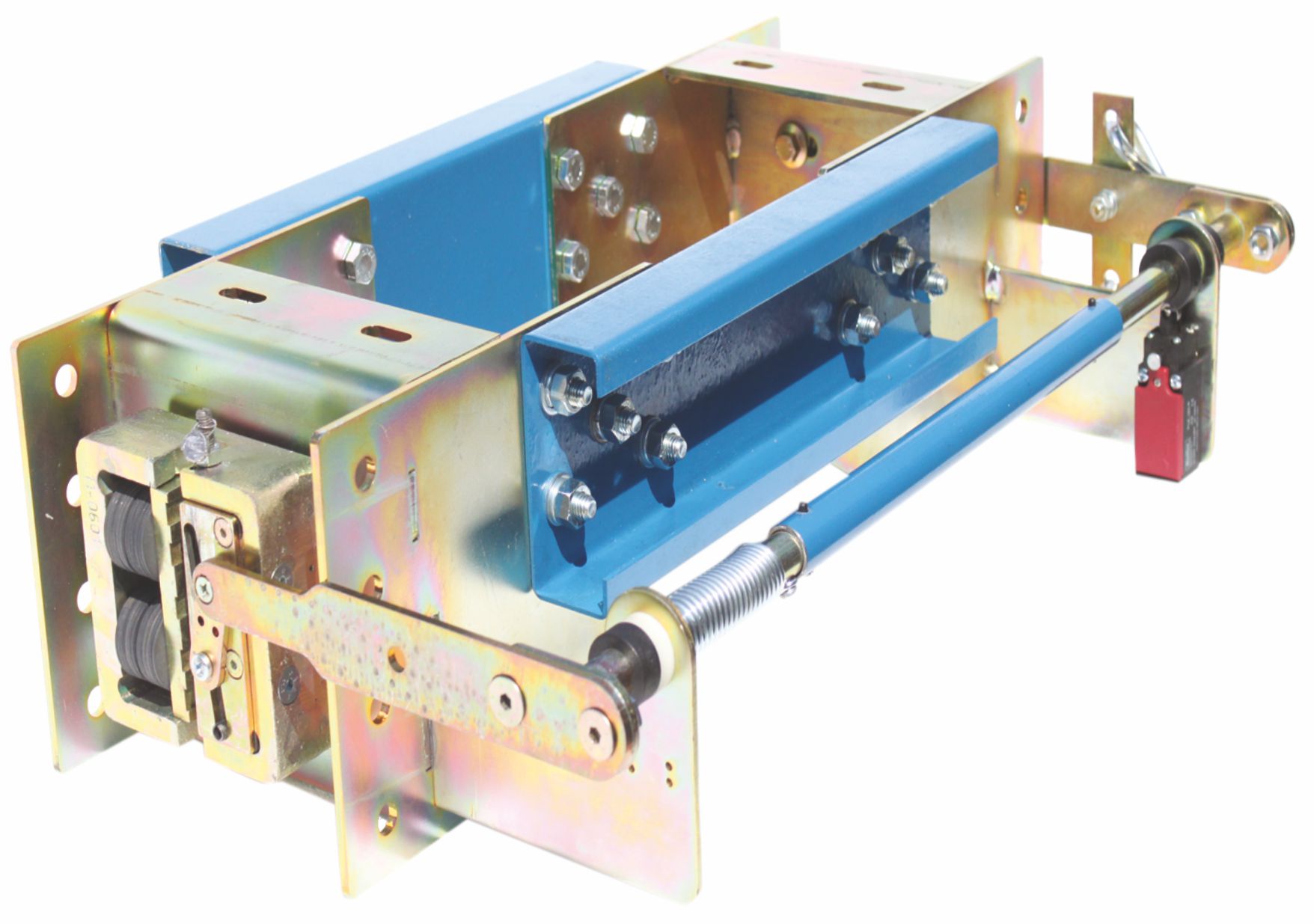
Figure 2: Challenging Z06-3 Progressive Safety Gear
When determining the P+Q value, P is calculated in kg as the sum of the masses of the empty cabin and the parts suspended in the cabin (such as flexible cable, etc.) carried by the cabin and the balancing chain, if any. Q is the car carrying capacity and the declared load of the elevator is taken in kg.
For example, the maximum P+Q value of the Z06-3 brake in figure2 for 16 mm thick 'machined' and oiled guide rails up to a nominal speed of 1.6 m/s is 3092 kg. The Z-06-3-T model in Figure-3 is a tandem set consisting of 2 Z-06 brake systems. The P+Q value of this product is twice as much as the first one, i.e. 6184 kg, because it is a tandem product. Of course, tandem PSG is not an application that applies to every brake system. The Notified Body issuing the EU Type Examination Certificates of the PSG shall approve this with Type Examination Certificates in order for the relevant brake to be tandem.
The sliding brake system, which is a mechanical system, can be mounted on the lower or upper support beams of the cabin suspension. If there are accessible cavities beneath the shaft, the counterweight should also be equipped with a sliding brake system and a separate set of overspeed governors shall be used to trigger this system.
In order to provide the minimum tension of 300 Nm required for the safety rope easily and for its continuity, it is strongly recommended by the safety gear manufacturers that the regulator lower tension pulley should be weighted type and positioned as far as possible ahead of the pulley, if the shaft bottom distance is sufficient; in addition, the steel core of the tension rope and the speed regulator pulley diameters should be 300 mm, and the safety rope diameter should be at least 8 mm in elevators with 10 or more stops.
Figure 3: Z06-3-T (Tandem) Z06-3 Progressive Safety Gear
As an engineer working in the manufacturing sector, I think that the cabin manufacturing companies should also manufacture the safety gears to be used in the cabin. In addition, I strongly recommend that PSG manufacturing companies accompany the Type Examination / Conformity Tests to be carried out by the Notified Body of the brakes they will design and certify. The manufacturer should see on site that the braking acceleration of the brake system under test goes beyond the range allowed by the standard, or even that the brake does not hold and the elevator crashes to the ground. The manufacturer, who will better comprehend the dimensions of the danger and the frighteningness of the event, will have the opportunity to see many negative scenarios that may occur in the future before the product is placed on the market. Moreover, there is no compensation for a disaster that may occur after the product is on the market.
References
- 2014/33/EU Lifts Directive
- TS EN 81-20:2020
- TS EN 81-50:2020
- Ministry of Industry and Technology letter dated 27.08.2018 and numbered 30968416- 622.03- E.29765,
- Progressive Safety Gear in Elevators and Design Problems, Fatih C. BABALIK, Kadir ÇAVDAR
- Manufacturer Catalogs (Zorlu, Wittur, Dynatech, Metroplast)
- Changes in Safety Devices and New Standards, Melih ZORLU, Elevator World Türkiye, July-August 2017